Perfusion bioreactor: Boosting efficient bioprocess results

Discover how perfusion bioreactor enhances efficiency and productivity in bioprocessing with advanced techniques and innovative methods

In the fast-paced world of biotechnology, achieving high efficiency and productivity in bioprocesses is crucial. Perfusion bioreactor is a new technique that is better than traditional batch and fed-batch methods in many ways.

By continuously exchanging the culture medium, perfusion systems keep cells in their optimal growth conditions. This not only boosts cell productivity but also improves the overall quality of the final product. Imagine being able to produce more with better consistency – that's the promise of perfusion technology.

Curious about how this works and what makes it so effective?

In this article, we’ll explore the basics of perfusion, its advantages, and the different types of perfusion systems. Whether you are experienced or new to bioprocessing, this guide will give you helpful tips to improve your processes.

What is perfusion?

Perfusion in cell culture is a method that maintains cells within a bioreactor while continuously exchanging the culture medium.

This process ensures that it replenishes nutrients and carbon sources with fresh medium, while removing cellular waste and depleted medium.

The exchange of medium is typically measured in vessel volumes per day (VVD). For example, perfusing 6 liters of medium daily into a system with a 3-liter working volume equals 2 VVD. This continuous refreshment of the medium helps sustain optimal cell growth and productivity.

Cell retention methods

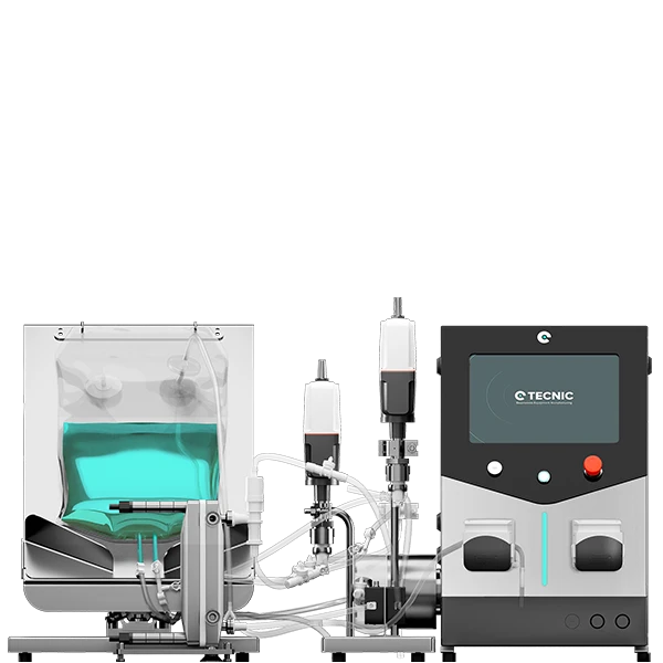
In suspension culture, there are two primary methods for retaining cells during perfusion: filtration and settling. Each method has its unique advantages and challenges.

Filtration

Filtration methods, such as tangential flow filtration (TFF), circulate the medium from the bioreactor through porous hollow fibers.

These fibers are designed to allow the medium to pass through while retaining the larger cells within the reactor.

The spent medium (permeate) flows across the membrane and is removed, while the cells cycle back into the reactor vessel.

Filtration methods provide fully clarified permeate that can be directly linked to downstream processing. This makes them ideal for processes where maintaining high cell density and product purity is essential.

Sedimention

Sedimentation techniques use gentle flows to help cells sink and collect. The settled cells are then returned to the bioreactor, while the remaining liquid is removed.

Settling methods are generally more cost-effective and have a lower risk of system fouling compared to filtration methods. However, they are less efficient at retaining cells, often resulting in some cell loss (referred to as "bleed") in the spent medium. Despite this drawback, settling methods can be advantageous for processes with lower cell density requirements and where cost reduction is a priority.

Types of perfusion

N-1 Perfusion

N-1 perfusion, also known as intensified seed train perfusion, focuses on achieving high cell densities while cells are in their logarithmic growth phase.

Usually, this procedure takes around 3 to 6 days and is employed to decrease the quantity of vessels needed in a seed train. This aids in achieving higher-density reactor seeding and creating high-density seed banks.

Key benefits include its simplicity, reduced equipment requirements, and the minimal need for medium optimization. This method is particularly useful for quickly generating high cell densities without emphasizing productivity.

Operational considerations

Operationally, N-1 perfusion maintains a high medium exchange rate to ensure cells remain in their optimal growth phase. The short duration simplifies logistics and minimizes the need for extensive equipment.

Additionally, it provides higher seeding densities to production reactors, which is advantageous for downstream processes. However, since productivity is not a primary concern, it is less suitable for the final production stages.

Concentrated fed-batch perfusion

Concentrated fed-batch perfusion uses alternating tangential flow filtration (ATF) or tangential flow filtration (TFF) to retain both cells and products within the bioreactor.

This method increases product amounts, making it great for stable products with low productivity in batch or fed-batch processes.

The concentrated environment enhances downstream processing efficiency by eliminating the need for additional concentration steps. Typically, this process runs for 14-20 days and targets high titers suitable for downstream applications.

Process requirements

Concentrated fed-batch perfusion is moderately complex, requiring ATF or TFF systems with filters that can retain the product within the vessel.

The medium exchange rate must be carefully controlled to achieve the desired product titers. This method works best for strong products that can handle intense conditions and has quality risks like fed-batch processes. Effective management of medium exchange is critical to maximizing titer and maintaining process stability.

Intensified fed-batch perfusion

Intensified fed-batch perfusion is like concentrated fed-batch, but with continuous product removal during the process.

This approach is advantageous for labile products and scenarios requiring high production concentration without additional downstream concentration steps. Shorter product retention times improve quality control and enable semicontinuous downstream purification. Run durations are generally 16-25 days, with medium exchange rates optimized for cost efficiency.

Comparison with concentrated fed-batch

Compared to concentrated fed-batch, intensified fed-batch offers higher total product generation and improved quality control due to continuous product removal.

Better suited for less stable products, as the reduced residence time lowers the risk of degradation. Additionally, it allows for the use of TFF or ATF filters to produce a clarified product stream ready for downstream processing. While both methods are moderately complex, intensified fed-batch tends to be more efficient and better for specific applications.

Continuous perfusion

Continuous perfusion aims to maintain steady-state conditions, ensuring consistent productivity and product quality over extended periods, typically ranging from 20 to 60 days.

This method uses a small amount of bleed to keep cells alive and at the right density, which helps improve efficiency. Optimized medium exchange rates ensure high efficiency and tight process control, making continuous perfusion ideal for long-term, stable production.

Long-term stability and efficiency

The primary advantage of continuous perfusion is its ability to sustain high product titers and quality with minimal variability. This method is particularly beneficial for integrating with continuous downstream bioprocessing.

Despite the longer time required for process optimization and the higher risk associated with extended operations, the benefits of superior quality control, reduced need for seed trains, and scalability make continuous perfusion a valuable option. Additionally, automation-friendly steady-state operations help mitigate the complexity, making it a viable choice for large-scale production.

Comparing perfusion techniques: Key differences and considerations

When it comes to optimizing bioprocesses, selecting the right type of perfusion is crucial.

Each perfusion technique, N-1 perfusion, concentrated fed-batch perfusion, intensified fed-batch perfusion, and continuous perfusion, offers unique advantages and operational considerations. Understanding these differences can help bioprocess engineers and project managers make informed decisions that enhance productivity, product quality, and efficiency.

The following table provides a comprehensive comparison of the four perfusion types, highlighting their primary goals, typical durations, medium exchange rates, complexity, cell retention methods, product removal strategies, suitability for labile products, quality control, operational considerations, scalability, risk of system fouling, and cost efficiency. This overview aims to guide you in selecting the most appropriate perfusion method for your specific bioprocess needs.

Feature/Aspect N-1 Perfusion Concentrated Fed-Batch Perfusion Intensified Batch Perfusion Continuous Perfusion
Primary Goal High cell densities Increased product titer Higher total product generation Steady-state productivity
Typical Duration 4-7 days 14-20 days 16-25 days 30-90 days
Medium Exchange Rate High, to maintain logarithmic growth Moderate, to achieve target final titers Optimized to minimize cost per gram of product Optimized for efficiency and control
Complexity Low Moderate Moderate High
Cell Retention Method Filtration or settling ATF or TFF ATF or TFF Typically filtration
Product Removal Not prioritized Retained in bioreactor Continuously removed Continuously removed
Suitability for Labile Products Less suitable Suitable Highly suitable Highly suitable
Product Quality Control Less emphasis Similar to fed-batch Improved due to continuous removal Superior due to steady-state
Operational Considerations Simplifies seed train operations Requires stable product, moderate run length Shorter retention improves quality, semicontinuous downstream Long optimization, automation-friendly
Scalability High High High High
Risk of System Fouling Low Moderate Moderate Moderate to High
Cost Efficiency High Moderate High Moderate, balanced by fewer seed trains

The impact of perfusion bioreactor on bioprocess efficiency

Perfusion bioreactor has revolutionized the field of bioprocessing by offering unparalleled efficiency, productivity, and product quality. This continuous method of culturing cells ensures a constant supply of fresh nutrients while removing waste, creating an optimal environment for cell growth and protein production.

Whether it's the rapid cell density increase in N-1 perfusion, the high product titers achieved with concentrated fed-batch, the enhanced control in intensified fed-batch, or the long-term stability of continuous perfusion, each technique provides unique benefits that cater to different stages and needs of bioprocessing.

By adopting perfusion bioreactor, bioprocess engineers can achieve higher yields, better consistency, and more efficient use of resources. As the biotechnology landscape evolves, mastering these perfusion techniques will be essential for staying ahead and driving forward innovations in biopharmaceutical production.

Bioreactor Perfusion FAQ

Frequently Asked Questions (FAQ)

1. What is bioreactor perfusion and how does it work?

Bioreactor perfusion is a continuous cell culture method that maintains optimal growth conditions by constantly supplying fresh nutrients and removing waste. This process enhances cell productivity and product quality by keeping the cells in an ideal environment.

2. What are the main advantages of using perfusion over traditional batch or fed-batch methods?

Perfusion offers several benefits, including higher cell densities, increased product yields, improved product quality, and more efficient use of resources. It also allows for better control over the production process and can be scaled more easily to meet production demands.

3. How do N-1 perfusion, concentrated fed-batch perfusion, intensified fed-batch perfusion, and continuous perfusion differ?

Each perfusion type has unique features: N-1 perfusion focuses on rapidly increasing cell density, concentrated fed-batch perfusion aims for high product titers, intensified fed-batch perfusion enhances product generation and quality control, and continuous perfusion maintains long-term steady-state production with high consistency.

4. What factors should be considered when choosing a perfusion method for a bioprocess?

Factors to consider include the specific production goals, the stability of the product, the required cell density, the duration of the production run, and the complexity of the operation. Each perfusion method has different strengths that can be matched to the needs of the process.

5. Can bioreactor perfusion be integrated with existing downstream processes?

Yes, bioreactor perfusion can be seamlessly integrated with downstream processes. Filtration methods used in perfusion provide clarified permeate that can be directly linked to downstream operations, improving overall process efficiency and product quality.

Related Stories

There are no posts on the list.

Quote

Quote

Coming soon 

We are finalizing the details of our new equipment. Soon, we will announce all the updates. If you want to receive all the latest news about our products, subscribe to our newsletter or follow our social media channels. 

Newsletter Form

Sign Up

Stay informed about our product innovations, best practices, exciting events and much more! After signing up for our newsletter, you can unsubscribe at any time.

Newsletter Form

Cassette

We understand the importance of flexibility and efficiency in laboratory processes. That's why our equipment is designed to be compatible with Cassette filters, an advanced solution for a variety of filtration applications. Although we do not manufacture the filters directly, our systems are optimized to take full advantage of the benefits that Cassette filters offer.

Cassette filters are known for their high filtration capacity and efficiency in separation, making them ideal for ultrafiltration, microfiltration, and nanofiltration applications. By integrating these filters into our equipment, we facilitate faster and more effective processes, ensuring high-quality results.

Our equipment, being compatible with Cassette filters, offers greater versatility and adaptability. This means you can choose the filter that best suits your specific needs, ensuring that each experiment or production process is carried out with maximum efficiency and precision.

Moreover, our equipment stands out for its 100% automation capabilities. Utilizing advanced proportional valves, we ensure precise control over differential pressure, transmembrane pressure, and flow rate. This automation not only enhances the efficiency and accuracy of the filtration process but also significantly reduces manual intervention, making our systems highly reliable and user-friendly.

Hollow Fiber

We recognize the crucial role of flexibility and efficiency in laboratory processes. That's why our equipment is meticulously designed to be compatible with Hollow Fiber filters, providing an advanced solution for a broad spectrum of filtration applications. While we don't directly manufacture these filters, our systems are finely tuned to harness the full potential of Hollow Fiber filters.

Hollow Fiber filters are renowned for their exceptional performance in terms of filtration efficiency and capacity. They are particularly effective for applications requiring gentle handling of samples, such as in cell culture and sensitive biomolecular processes. By integrating these filters with our equipment, we enable more efficient, faster, and higher-quality filtration processes.

What sets our equipment apart is its 100% automation capability. Through the use of sophisticated proportional valves, our systems achieve meticulous control over differential pressure, transmembrane pressure, and flow rate. This level of automation not only boosts the efficiency and precision of the filtration process but also significantly diminishes the need for manual oversight, rendering our systems exceptionally reliable and user-friendly.

Contact General

Cellular configuration

The cellular configuration of the eLab Advanced is equipped with a pitched-blade impeller designed to support efficient mixing for cell culture processes in both laboratory development and early scale-up. The blade geometry promotes mainly axial flow, helping to distribute gases, nutrients and pH control agents uniformly throughout the vessel while keeping shear stress at a moderate level. This makes it suitable for mammalian, insect and other shear-sensitive cell lines when operated with appropriate agitation and aeration settings. In combination with the vessel aspect ratio and baffle design, the pitched blade supports stable foaming behavior and reproducible oxygen transfer, which is essential when comparing batches or transferring processes between working volumes.

Operators can fine-tune agitation speed to balance oxygen demand and mixing time without excessively increasing mechanical stress on the culture. 

Microbial configuration

The microbial configuration of the eLab Advanced is equipped with a Rushton turbine specifically designed for high-oxygen-demand processes such as bacterial and yeast fermentations. The radial-flow impeller generates strong mixing and intense gas dispersion, promoting high oxygen transfer rates and fast homogenization of nutrients, antifoam and pH control agents throughout the vessel. This makes it particularly suitable for robust microbial strains operating at elevated agitation speeds and aeration rates.

Operators can adjust agitation and gas flow to reach the required kLa while maintaining consistent mixing times, even at high cell densities. This configuration is an excellent option for users who need a powerful, reliable platform to develop and optimize microbial processes before transferring them to pilot or production scales.

Technical specifications

Materials and finishes

Typical
  • Product-contact parts: AISI 316L (1.4404), typical Ra < 0.4 µm (16 µin)
  • Non-contact parts/skid: AISI 304/304L
  • Seals/elastomers: platinum-cured silicone, EPDM and/or PTFE (material set depends on selection)
  • Elastomers compliance (depending on selected materials): FDA 21 CFR 177.2600 and USP Class VI
  • Surface treatments: degreasing, pickling and passivation (ASTM A380 and ASTM A968)
  • Roughness control on product-contact surfaces

Design conditions

Pressure & temperature

Defined considering non-hazardous process fluids (PED group 2) and jacket steam/superheated water (PED group 5), depending on configuration and project scope.

Reference design envelope
Mode Element Working pressure (bar[g]) Working pressure (psi[g]) T max (°C / °F)
ProcessVessel0 / +2.50 / +36.3+90 / 194
ProcessJacket0 / +3.80 / +55.1+90 / 194
SterilisationVessel0 / +2.50 / +36.3+130 / 266
SterilisationJacket0 / +3.80 / +55.1+150 / 302
Jacket working pressure may also be specified as 0 / +4 bar(g) (0 / +58.0 psi[g]) depending on design selection; final values are confirmed per project.

Pressure control and safeguards

Typical
  • Designed to maintain a vessel pressure set-point typically in the range 0 to 2.5 bar(g)
  • Aseptic operation commonly around 0.2 to 0.5 bar(g) to keep the vessel slightly pressurised
  • Overpressure/underpressure safeguards included per configuration and regulations
  • Pressure safety device (e.g., rupture disc and/or safety valve) included according to configuration

Agitation

Reference ranges
Working volume MU (Cell culture), reference MB (Microbial), reference
10 L0 to 300 rpm0 to 1000 rpm
20 L0 to 250 rpm0 to 1000 rpm
30 L0 to 200 rpm0 to 1000 rpm
50 L0 to 180 rpm0 to 1000 rpm

Integrated peristaltic pumps (additions)

Typical

The equipment typically includes 4 integrated variable-speed peristaltic pumps for sterile additions (acid/base/antifoam/feeds). Actual flow depends on selected tubing and calibration.

Parameter Typical value Notes
Quantity 4 units (integrated) In control tower; assignment defined by configuration
Speed 0-300 rpm Variable control from eSCADA
Minimum flow 0-10 mL/min Example with 0.8 mm ID tubing; depends on tubing and calibration
Maximum flow Up to ~366 mL/min Example with 4.8 mm ID tubing; actual flow depends on calibration
Operating modes OFF / AUTO / MANUAL / PROFILE AUTO typically associated to pH/DO/foam loops or recipe
Functions PURGE, calibration, totaliser, PWM PWM available for low flow setpoints below minimum operating level

Gas flow control (microbial reference capacity)

Reference

For microbial culture (MB), gas flow controllers (MFC) are typically sized based on VVM targets. Typical reference VVM range: 0.5-1.5 (to be confirmed by process).

Working volume (L) VVM min VVM max Air (L/min) O2 (10%) (L/min) CO2 (20%) (L/min) N2 (10%) (L/min)
100.51.55-150.5-1.51-30.5-1.5
200.51.510-301-32-61-3
300.51.515-451.5-4.53-91.5-4.5
500.51.525-752.5-7.55-152.5-7.5
O2/CO2/N2 values are shown as reference capacities for typical gas blending strategies (10% O2, 20% CO2, 10% N2). Final gas list and ranges depend on process and configuration.

Instrumentation and sensors

Typical

Instrumentation is configurable. The following list describes typical sensors integrated in standard configurations, plus common optional PAT sensors.

Variable / function Typical technology / interface Status (STD/OPT)
Temperature (process/jacket)Pt100 class A RTDSTD
Pressure (vessel/lines)Pressure transmitter (4-20 mA / digital)STD
Level (working volume)Adjustable probeSTD
pHDigital pH sensor (ARC or equivalent)STD
DO (pO2)Digital optical DO sensor (ARC or equivalent)STD
FoamConductive/capacitive foam sensorSTD
Weight / mass balanceLoad cell (integrated in skid)STD
pCO2Digital pCO2 sensor (ARC or equivalent)OPT
Biomass (permittivity)In-line or in-vessel sensorOPT
VCD / TCDIn-situ cell density sensorsOPT (MU)
Off-gas (O2/CO2)Gas analyser for OUR/CEROPT
ORP / RedoxDigital ORPOPT
Glucose / LactatePAT sensorOPT

Automation, software and connectivity

Typical

The platform incorporates TECNIC eSCADA (typically eSCADA Advanced for ePILOT) to operate actuators and control loops, execute recipes and manage process data.

Main software functions
  • Main overview screen with process parameters and trends
  • Alarm management (real-time alarms and historical log) with acknowledgement and comment option
  • Manual/automatic modes for actuators and control loops
  • Recipe management with phases and transitions; parameter profiles (multi-step) for pumps and setpoints
  • Data logging with configurable period and export to CSV; PDF report generation
Common control loops
  • Temperature control (jacket heating/cooling)
  • Pressure control (headspace) with associated valve management
  • pH control via acid/base addition pumps and optional CO2 strategy
  • DO control with cascade strategies (agitation, air, O2, N2) depending on package and configuration
  • Foam control (foam sensor and automatic antifoam addition)
Data integrity and 21 CFR Part 11

Support for 21 CFR Part 11 / EU GMP Annex 11 is configuration- and project-dependent and requires customer procedures and validation (CSV).

Utilities

Reference

Utilities depend on final configuration (e.g., AutoSIP vs External SIP) and destination market (EU vs North America). The following values are typical reference points.

Utility Typical service / configuration Pressure Flow / power Notes
Electrical EU base: 400 VAC / 50 Hz (3~) N/A AutoSIP: 12 kW; External SIP: 5 kW NA option: 480 VAC / 60 Hz; cabinet/wiring per NEC/NFPA 70; UL/CSA as required
Process gases Air / O2 / CO2 / N2 Up to 2.5 bar(g) (36.3 psi) According to setpoint Typical OD10 pneumatic connections; final list depends on package
Instrument air Pneumatic valves Up to 6 bar(g) (87.0 psi) N/A Dry/filtered air recommended
Cooling water Jacket cooling water 2 bar(g) (29.0 psi) 25 L/min (6.6 gpm) 6-10 °C (43-50 °F) typical
Cooling water Condenser cooling water 2 bar(g) (29.0 psi) 1 L/min (0.26 gpm) 6-10 °C (43-50 °F) typical
Steam (External SIP) Industrial steam 2-3 bar(g) (29.0-43.5 psi) 30 kg/h (66 lb/h) For SIP sequences
Steam (External SIP) Clean steam 1.5 bar(g) (21.8 psi) 8 kg/h (18 lb/h) Depending on plant strategy

Compliance and deliverables

Typical

Depending on destination and project scope, the regulatory basis may include European Directives (CE) and/or North American codes. The exact list is confirmed per project and stated in the Declaration(s) of Conformity when applicable.

Scope EU (typical references) North America (typical references)
Pressure equipmentPED 2014/68/EUASME BPVC Section VIII (where applicable)
Hygienic designHygienic design good practicesASME BPE (reference for bioprocessing)
Machine safetyMachinery: 2006/42/EC (until 13/01/2027) / (EU) 2023/1230OSHA expectations; NFPA 79 (industrial machinery) - project dependent
Electrical / EMCLVD 2014/35/EU; EMC 2014/30/EUNEC/NFPA 70; UL/CSA components and marking as required
Materials contactEC 1935/2004 + EC 2023/2006 (GMP for materials) where applicableFDA 21 CFR (e.g., 177.2600 for elastomers) - materials compliance
Software / CSVEU GMP Annex 11 (if applicable)21 CFR Part 11 (if applicable)
Standard documentation package
  • User manual and basic operating instructions
  • P&ID / layout drawings as per project scope
  • Material certificates and finish/treatment certificates (scope dependent)
  • FAT report (if included in contract)
Optional qualification and commissioning services
  • SAT (Site Acceptance Test)
  • IQ / OQ documentation and/or execution (scope agreed with customer)
  • CSV support package for regulated environments (ALCOA+ considerations, backups, time synchronisation, etc.)

Ordering and configuration

Project-based

ePILOT BR is configured per project. To define the right MU/MB package, volumes and options (utilities, sensors, software and compliance), please contact TECNIC with your URS or request the configuration questionnaire.

The information provided above is for general reference only and may be modified, updated or discontinued at any time without prior notice. Values and specifications are indicative and may vary depending on project scope, configuration and applicable requirements. This content does not constitute a binding offer, warranty, or contractual commitment. Any final specifications, deliverables and acceptance criteria will be confirmed in the corresponding quotation, technical documentation and/or contract documents.

Cellular configuration

The cellular configuration of the eLab Advanced is equipped with a pitched-blade impeller designed to support efficient mixing for cell culture processes in both laboratory development and early scale-up. The blade geometry promotes mainly axial flow, helping to distribute gases, nutrients and pH control agents uniformly throughout the vessel while keeping shear stress at a moderate level. This makes it suitable for mammalian, insect and other shear-sensitive cell lines when operated with appropriate agitation and aeration settings. In combination with the vessel aspect ratio and baffle design, the pitched blade supports stable foaming behavior and reproducible oxygen transfer, which is essential when comparing batches or transferring processes between working volumes.

Operators can fine-tune agitation speed to balance oxygen demand and mixing time without excessively increasing mechanical stress on the culture. 

Technical specifications

[contact-form-7 id="c5c798c" title="ePilot BR configuration questionnaire"]

Cellular configuration

The cellular configuration of the eLab Advanced is equipped with a pitched-blade impeller designed to support efficient mixing for cell culture processes in both laboratory development and early scale-up. The blade geometry promotes mainly axial flow, helping to distribute gases, nutrients and pH control agents uniformly throughout the vessel while keeping shear stress at a moderate level. This makes it suitable for mammalian, insect and other shear-sensitive cell lines when operated with appropriate agitation and aeration settings. In combination with the vessel aspect ratio and baffle design, the pitched blade supports stable foaming behavior and reproducible oxygen transfer, which is essential when comparing batches or transferring processes between working volumes.

Operators can fine-tune agitation speed to balance oxygen demand and mixing time without excessively increasing mechanical stress on the culture. 

Technical specifications

Models and working volumes

Tank

The ePlus Mixer platform combines an ePlus Mixer control tower with Tank frames and eBag 3D consumables. Tank can be supplied in square or cylindrical configurations (depending on project) to match the bag format.

Tank model Nominal volume Minimum volume to start agitation*
Tank 50 L50 L15 L
Tank 100 L100 L20 L
Tank 200 L200 L30 L
Tank 500 L500 L55 L
*Values based on agitation start interlocks per tank model. Final performance depends on the selected eBag 3D, fluid properties and configuration.

Design conditions and operating limits

Reference

Reference limits are defined for the ePlus Mixer and the Tank. It is recommended to validate the specific limits of the selected eBag 3D and single-use sensors for the customer’s process.

Element Operating pressure Maximum pressure (safety) Maximum working temperature
ePlus Mixer (control tower)ATM0.5 bar(g)90 °C
TankATM0.5 bar(g)45 °C
Jacket (if applicable)N/A1.5 barDepends on utilities / scope
The 0.5 bar(g) limit is associated with the equipment design, the circuit is protected by a safety valve. Confirm final limits on the equipment nameplate and project specification.

Materials and finishes

Typical
  • Control tower housing and frame: stainless steel 304
  • Product-contact metallic hard parts (if applicable): stainless steel 316 (defined in project manufacturing documentation)
  • Non-product-contact metallic parts: stainless steel 304
  • eBag consumable: single-use polymer (supplier dependent, gamma irradiation / sterilisation per specification)
  • Vent filters: PP (polypropylene), per component list
For GMP projects, the recommended documentation package includes material certificates, surface finish certificates (Ra if applicable) and consumable sterility/irradiation certificates.

Agitation system

Magnetic

Non-invasive magnetic agitation, the impeller is integrated in the eBag 3D Mixer format, avoiding mechanical seals. Agitation speed is controlled from the HMI, with start interlocks linked to the tank model and minimum volume.

Reference speed range
  • Typical agitation range: 120 to 300 rpm (configuration dependent)
  • Magnetic drive motor (reference): Sterimixer SMA 85/140, 50 Hz, 230/400 V, 0.18 kW
  • Gear reduction (reference): 1:5
  • Actuation (reference): linear actuator LEYG25MA, stroke 30–300 mm, speed 18–500 mm/s (for positioning)
Final rpm and mixing performance depend on tank size, bag format and process requirements.

Weighing and volume control

Integrated

Weight and derived volume control are performed using 4 load cells integrated in the tank frame legs and a weight indicator. Tare functions are managed from the HMI to support preparation steps and additions by mass.

Component Reference model Key parameters
Load cells (x4) Mettler Toledo SWB505 (stainless steel) 550 kg each, output 2 mV/V, IP66
Weight indicator Mettler Toledo IND360 DIN Acquisition and HMI display, tare and “clear last tare”
For installation engineering, total floor load should consider product mass + equipment mass + margin (recommended ≥ 20%).

Pumps and fluid handling

Standard

The platform includes integrated pumps for additions and circulation. Final tubing selection and calibration define the usable flow range.

Included pumps (reference)
  • 3 integrated peristaltic pumps for additions (acid/base/media), with speed control from HMI
  • 1 integrated centrifugal pump for circulation / transfer (DN25)
Peristaltic pumps (reference)
Parameter Reference Notes
Quantity3 unitsIntegrated in the control tower
Pump headHYB101 (Hygiaflex)Example tubing: ID 4.8 mm, wall 1.6 mm
Max speed300 rpmSpeed control reference: 0–5 V
Max flow (example)365.69 mL/minDepends on tubing and calibration
Centrifugal pump (reference)
Parameter Reference
ModelEBARA MR S DN25
Power0.75 kW
FlowUp to 42 L/min
PressureUp to 1 bar
For circulation and sensor loops, the eBag 3D format can include dedicated ports (depending on the selected consumable and application).

Thermal management (optional jacket)

Optional

Tank can be supplied with a jacket (single or double jacket options). The thermal circuit includes control elements and a heat exchanger, enabling temperature conditioning depending on utilities and project scope.

  • Jacket maximum pressure (reference): 1.5 bar
  • Thermal circuit safety: pressure regulator and safety valve (reference set-point 0.5 bar(g))
  • Heat exchanger (reference): T5-BFG, 12 plates, alloy 316, 0.5 mm, NBRP
  • Solenoid valves (reference): SMC VXZ262LGK, 1", DC 24 V, 10.5 W
  • Jacket sequences: fill / empty / flush (scope dependent)
The tank maximum temperature may depend on the thermal circuit and consumable limits. Confirm final values with the selected eBag 3D specification.

Instrumentation and sensors

Optional SU

Single-use sensors can be integrated via dedicated modules. The following references describe typical sensors and interfaces listed in the datasheet.

Variable Reference model Interface / protocol Supply Operating temperature IP
pH OneFerm Arc pH VP 70 NTC (SU) Arc Module SU pH, Modbus RTU 7–30 VDC 5–50 °C IP67
Conductivity Conducell-P SU (SU) Arc Module Cond-P SU, Modbus RTU 7–30 VDC 0–60 °C IP64
Temperature Pt100 ø4 × 52 mm, M8 (non-invasive) Analog / acquisition module Project dependent Project dependent Project dependent
Measurement ranges and final sensor list depend on the selected single-use components and project scope.

Automation, software and data

Standard + options

The ePlus SUM control tower integrates an industrial PLC and touch HMI. Standard operation supports Manual / Automatic / Profile modes, with optional recipe execution depending on selected software scope.

Software scope (reference)
  • Standard: eBASIC (base HMI functions)
  • Optional: eSCADA Basic or eSCADA Advanced (project dependent)
  • Trends, alarms and profiles, profiles up to 100 steps (depending on scope)
  • Data retention (reference): up to 1 year
Connectivity (reference)
  • Industrial Ethernet and integrated OPC server (included)
  • Remote access option (project dependent)

Utilities and facility interfaces

Typical

Installation requirements depend on jacket and temperature scope and the customer layout. The following values are typical references.

Utility Pressure Flow Connections Notes
Electrical supply N/A Reference: 18 A 380–400 VAC, 3~ + N, 50 Hz Confirm per final configuration and destination market
Ethernet N/A N/A RJ45 OPC server, LAN integration
Tap water 2.5 bar N/A 1/2" (hose connection) Jacket fill and services, tank volume about 25 L
Cooling water 2–4 bar 10–20 L/min 2 × 3/4" (hose connection) Heat exchanger and jacket cooling
Process air 2–4 bar N/A 1/2" quick coupling Used for jacket emptying
Drain N/A N/A 2 × 3/4" (hose connection) For draining
Exhaust N/A N/A N/A Optional (depending on project)
Stack light (optional) N/A N/A N/A 3-colour indication, as per scope
During FAT, verify in the installation checklist that the available utilities match the selected configuration and scope.

Documentation and deliverables

Project-based

Deliverables depend on scope and project requirements. The following items are typical references included in the technical documentation package.

  • Datasheet and user manual (HMI and system operation)
  • Electrical schematics, PLC program and backup package (scope dependent)
  • P&ID, layout and GA drawings (PDF and/or CAD formats, project dependent)
  • Factory Acceptance Test (FAT) protocol and FAT report (as per contract)
  • Installation checklist
  • Material and consumable certificates, as required for regulated projects (scope dependent)
On-site services (SAT, IQ/OQ) and extended compliance packages are optional and defined per project.

Ordering and configuration

Contact

The ePlus Mixer scope is defined per project. To select the right tank size, bag format, sensors and optional jacket and software, please share your URS or request the configuration questionnaire.

The information provided above is for general reference only and may be modified, updated or discontinued at any time without prior notice. Values and specifications are indicative and may vary depending on project scope, configuration and applicable requirements. This content does not constitute a binding offer, warranty, or contractual commitment. Any final specifications, deliverables and acceptance criteria will be confirmed in the corresponding quotation, technical documentation and/or contract documents.

Operating windows microbial vs. cell culture

The operating range depends on the volume, gas configuration and impeller type. Typical performance references and operating parameters for both applications are summarised below (guideline values; final performance depends on medium, antifoam, geometry and aeration strategy).

Performance and parameters:

Indicative operating windows for cellular and microbial processes. Final values depend on bag configuration, impellers, aeration strategy and process targets.

Application

Cell culture

Agitation (rpm)

300: 0–450
1000: 0–300

Tip speed (m/s)

0.4–1.8

P/V (W/m³)

80–200

kLa (h⁻¹)

20–30

Application

Microbial

Agitation (rpm)

300: 0–450
1000: 0–300

Tip speed (m/s)

1.5–5.0

P/V (W/m³)

1,000–5,500

kLa (h⁻¹)

150–330

Typical gas line ranges by model and application. Installed ranges and gas setup depend on selected options and project scope.

Gas

Process air

Typical range (Ln/min)

300 L: 20–300 (up to 600 depending on configuration)
1000 L: 20–1000 (up to 2000 depending on configuration)

Main use

Aeration by sparger / mixing

Notes by application

Microbial: primary. 

Cellular: DO support.

Gas

Oxygen (O₂)

Typical range (Ln/min)

300 L: 2–30 (up to 600 depending on configuration)
1000 L: 2–100 (up to 2000 depending on configuration)

Main use

DO enrichment and cascade

Notes by application

Microbial: frequent. Cellular: cascade at DO set point.

Gas

Carbon dioxide (CO₂)

Typical range (Ln/min)

300 L: 2–30 (typical) / 10–150 (depending on configuration)
1000 L: 2–100 (typical) / 10–500 (depending on configuration)

Main use

pH control / CO₂ balance

Notes by application

Cellular: standard. Microbial: optional.

Gas

Overlay (air or O₂)

Typical range (Ln/min)

300 L: 10–150
1000 L: 10–500

Main use

Headspace scavenging / gas control

Notes by application

Cellular: standard. Microbial: optional.

Note: the exact flow and gas ranges installed depend on the model and the options purchased.


Multi Use Bioreactors

Single Use Bioreactors

Multi Use TFF Systems

Single Use TFF Systems

Single-use bioprocess bags (2D and 3D)

Designed to enhance our bioprocess solutions

Versatile and reliable bioreactor vessels for bioprocessing

Versatile and reliable bioreactor vessels for bioprocessing